Tolerances And Helicopter Blueprints
A tolerance is the amount of material that can be added to, or subtracted from, a nominal dimension.
Manufactured parts may vary according to the tolerances shown on prints. Tolerances are necessary because it’s not practical to manufacture parts without some variations.
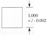
Figure 1. A plus or minus tolerance.
Tolerances allow parts to be interchangeable, which is an important factor in manufacturing and maintenance.
Tolerances are based on several factors such as the end use of the part, cost, how it’s manufactured, and the engineers’ expectations of the experience level of the builder.
Types of Tolerances
There are three types of tolerances:
- Plus or minus
- Maximum or minimum limits
- Only a maximum or only a minimum dimension
Plus or Minus
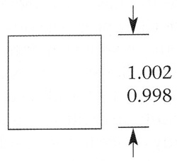
Figure 2. Tolerances may be shown as maximum and minimum dimensions.
A plus or minus tolerance is shown with a nominal dimension and indicates the amount of material that can be added to or subtracted from the nominal dimension.
See Figure 1. The example shown has a nominal dimension of 1.000 and a tolerance of plus or minus 0.002. This makes the maximum dimension 1.002, and the minimum dimension 0.998.
Parts that measure 1.002, 0.998, or anywhere in between are acceptable in this example. Parts larger than 1.002 or smaller than 0.998 are not acceptable.
A tolerance may have a plus figure and a minus zero, such as plus 0.002 and minus 0.000. Or it may have a plus zero and a minus figure, such as plus 0.000 and minus 0.002.
Maximum and Minimum Limits
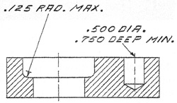
Figure 3. A tolerance may be shown as only a maximum or only a minimum dimension.
Tolerances may be shown as maximum and minimum dimensions, and in this form they are called limits and do not require additional calculations.
Only a Maximum or Only a Minimum Dimension
A tolerance may be shown as only a maximum or only a minimum dimension. This type is used when a tolerance is needed in only one direction.
The label for the 0.500 – diameter hole in Figure 3 must be at least 0.750 deep for parts to be properly assembled.
Methods of Displaying Tolerances
Tolerances may be displayed in three ways. You may see more than one method used in one print.
Unless otherwise specified:
- One place decimals + / – 0.1
- Two place decimals + / – 0.03
- Three place decimals + / – 0.008
- Angles + 1-2 degrees
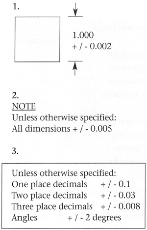
Figure 4. Tolerances may be shown in three ways.
On a blueprint, you may find tolerances displayed in a number of ways including, but not limited to, with a dimension, in a separate note, or within a title block.
Tolerances that are important to the function of a part are shown with a dimension. A typical manufacturing part may have one or two critical dimensions that are best displayed with a tolerance. This method provides the most practical way of displaying critical allowable variations.
Tolerances may also be shown as a separate note. This method is used if no title block or special requirements are needed. Most industrial blueprints have a title block containing a set of tolerances (Figure 4).
These tolerances are called general tolerances. They apply to all dimensions that do not have a tolerance or are not included in a separate note. General tolerances are rather broad and are not used for critical dimensions.
General tolerances may contain one set of figures if all dimensions have the same number of decimal places. If a drawing has dimensions with different decimal places, general tolerances are displayed as shown in Figure 4.
[FreshProduct productGroup=”blueprint_1517379107″ showimage=”yes” showprice=”yes” showtitle=”yes” align=”right” buttonclass=”” buttontext=”Buy Now” newwindow=”_self”]
Other Tolerance Expressions
-
Metric: Metric tolerances use millimeters and are displayed in the same general manner as those for inches.
-
Angles: Tolerances for angles are expressed in degrees and are displayed similar to tolerances for inches.
-
Form: Tolerances are expressed in the same form as the dimension. Fraction dimensions have fraction tolerances. Decimal tolerances have the same number of decimal places as the dimension (see Figure 4).
It’s important to understand tolerances because their interpretation may make the difference between acceptable or unacceptable parts.


Be the first to comment on "Blueprint Reading Basics"